BtoB Clip is durable and can significantly reduce the total cost of jig maintenance by using a high quality probe without using the connector on the other side.
If you use Other side connector
- Poor workability because visibility is bad
- There can damage the inspection side
- of the connector when removing
- the inspection after the connector.
- Low durability
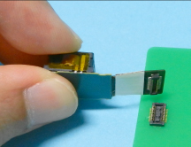
When we use our product
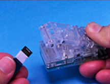
- Improved visibility is good workability
- Just easily bite as a clothespin!
- Since the lock mechanism
- is not there is no worry damage to
- the inspection side of the connector.
- High durability (200,000 tests clear)
Recommended for use in the following cases
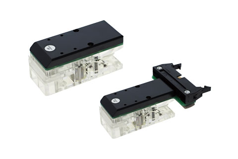
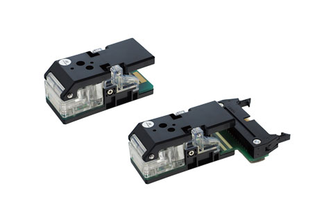
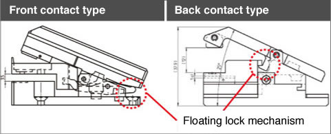
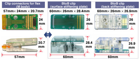
Surface stiffening plate (top contact)
the inspection item and the connector are mounted on the same plane (requires a connection to an extremely low-profiled connector)
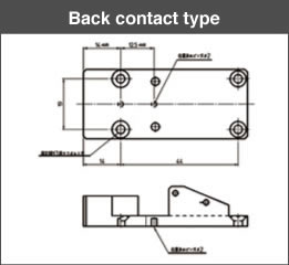
Back stiffening plate (bottom contact)
The inspection item and the connector are mounted on opposite planes (the inspection item and the connector are located in close proximity)
Features

- Connector mounting displacement absorption structure
Due to a structure that guides the connector external form as it is inserted, inspections are unaffected by mounting displacement between the connector and board (FPC). - Wide space for inspection item placement
The wide area allocated for mounting of the board (FPC) makes placing the inspection item easy. - Wide opening area
The opening part is expanded to improve working efficiency. - Probe protection structure
Surface stiffening plate: The guide shape is configured to prevent incorrect insertion of the inspection item. - Back stiffening plate
Since the guide tends to float, a structure has been adopted that prevents a probe from directly touching the connector when the inspection item is placed into position. - Floating lock mechanism
The guide part (floating guide) is configured so that it does not descend when the inspection item is placed into position. (Applies only at full-open time.)
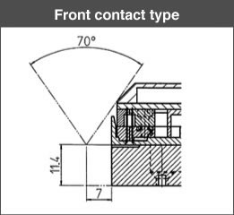
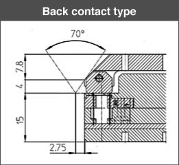
- Superior visibility
Height has been minimized, and the top front-end part is cut to improve visibility of the inspection item. By accounting for inspections by camera modules, we have devised a way to avoid affecting the angle of view.
*Angles of view up to 70° are supported even when the center of lens is close to a position 2.75 mm from the BtoB clip end face.
- Probes can be swapped while leaving the base intact
- Since the structure accommodates probes, when the base part is attached to an inspection device, the probe can be exchanged. This eliminates position adjustments at each probe replacement.
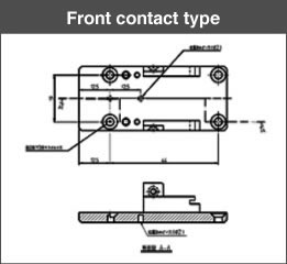
- Positioning pins installable
- A 2-mm diameter hole is provided for positioning pins opened to allow precise placement at a desired position.
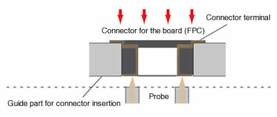
Probe contact position
Depending on the solidity of the solder applied, a probe with mild spring pressure is moved against the top of the connector terminal, rather than an instable connector lead.
Wiring type
for discrete wiring
pad-fitted type
Relationship between Pin Numbers and Fitted FRC connectors
| Target pin number | Connectors used |
|---|---|
| 10 to 32 pins | HIF6-32PA-1.27DS |
| 34 to 40 pins | HIF6-40PA-1.27DS |
| 42 to 60 pins | HIF6-60PA-1.27DS |
General Specification
| Maximum rated power | MAX.10W |
| Maximum rated current | 0.5A |
| Maximum rated voltage | 50V(AC/DC) |
| Withstand voltage | AC100V/1min |
| Insulation resistance | MIN100MΩ |
| Contact resistance | MAX.500mΩ(contact part) |
| Working temperature range | 0~85℃ |